| Duct Design Data
|
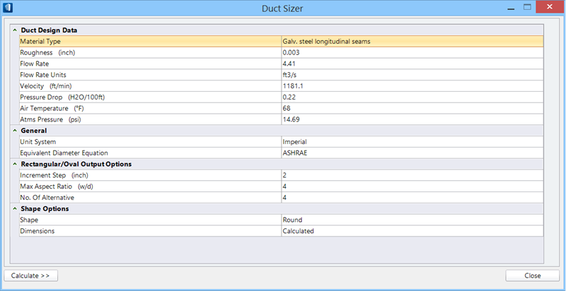
Defines the duct data settings used for sizing duct.
- Material
Type — Sets the material type for the duct.
-
Roughness — Sets the roughness of the
duct material.
The unit assigned is inch for Imperial and mm
for Metric.
-
Flow Rate — Sets the value for rate of
flow and unit of flow.
-
Flow Rate Units — The Imperial unit can
be selected as ft3/min or fl3/sec, and the Metric unit m3/s, m3/hr or l/s
respectively.
Tip: You can set default flow rate
units using the
BMECH_FLOWRATE_UNIT
configuration variable.
-
Velocity — Sets the velocity with which the flow travels in the
ducts.
The unit assigned per currently set under Unit
System – ft/min for Imperial and m/s for Metric.
-
Pressure Drop — Sets the pressure drop
value along the duct flow.
The unit assigned per currently set under Unit
System – H2O/100ft for Imperial and pa/m for Metric.
- Air
Temperature — Sets the temperature of air in flow system.
The unit assigned is ºF for Imperial and ºC for
Metric.
-
Atms Pressure — Sets the value for
atmospheric pressure to effect compute realistic duct performance.
The unit assigned per currently set under Unit
System – psi for Imperial and mbar for Metric.
|
| General
|
- Unit
System — Displays the units being used in duct sizing computing.
When toggled applies one of the unit system.
- Imperial —
Displays and apply imperial measurement units.
- Metric —
Displays and apply metric measurement units.
- Equivalent Diameter
Equation — Defines a standard to compute the duct sizing equating
the equation from two given standards.
- CIBSE — When
on, applies the CIBSE standards equation in computing the duct sizings.
- ASHRAE — When
on, applies the ASHRAE standards equation in computing the duct sizings.
|
| Fixed Dimensions
|
Sets fixed values that define dimension of the
duct.
- Use Fixed Value —
When on, enables dimension fields for selected shape option. For rectangular
ducts, the dimensions override the Rectangular Criteria set.
Note: The units in the bracket reflect the units
assigned to the dimensions as per selected unit system; inch for Imperial and
mm for Metric.
|
| Rectangular/Oval Output Options
|
Defines the duct data settings used for sizing
rectangular duct.
|
| Shape Option
|
- Shape — Defines
one of the shapes to ducts, among three standard shapes.
- Circular — When
on, assigns round shape to duct being sized.
- Rectangular —
When on, assigns rectangular shape to duct being sized.
- Oval — When on,
assigns oval shape to duct being sized.
- Dimensions —
Sets fixed values that define dimension of the duct.
- Fixed —
Populates dimension fields for selected shape option.
For Round ducts:
- Diameter —
Appears when Circular Shape option is selected. Sets diameter for the round
duct.
For Rectangular and Flat Oval ducts:
- Width —
Appears when Rectangular or Oval Shape option is selected. Sets width dimension
for the rectangular / oval duct.
- Depth —
Appears when Rectangular or Oval Shape option is selected. Sets depth dimension
for the rectangular / oval duct. The aspect ratio in the result is the width to
depth ratio of a rectangular / oval duct.
- Calculated —
Assigns calculated duct dimension values. Effect upon Calculate.
|
| Calculate
|
Computes the duct size according to the parameters
set.
|
 Used to calculate duct
sizes for transfer, supply, and return duct routes by computing duct sizes for
centerline routing, resizing by optimizing route path duct sections. Used in
3D-routed duct system consisting of connected components to compute and list
the Velocity Pressure exiting change-in-flow or change-in-size components
in the interactive tables.
Used to calculate duct
sizes for transfer, supply, and return duct routes by computing duct sizes for
centerline routing, resizing by optimizing route path duct sections. Used in
3D-routed duct system consisting of connected components to compute and list
the Velocity Pressure exiting change-in-flow or change-in-size components
in the interactive tables.